Connection Guide
This brief connection guide explains how to connect the wiring for all all the hardware components to the Beaglebone Blue embedded computer. This includes:
The Electronic Speed Controllers (ESCs)
Optional: The Mission Computer
ESCs
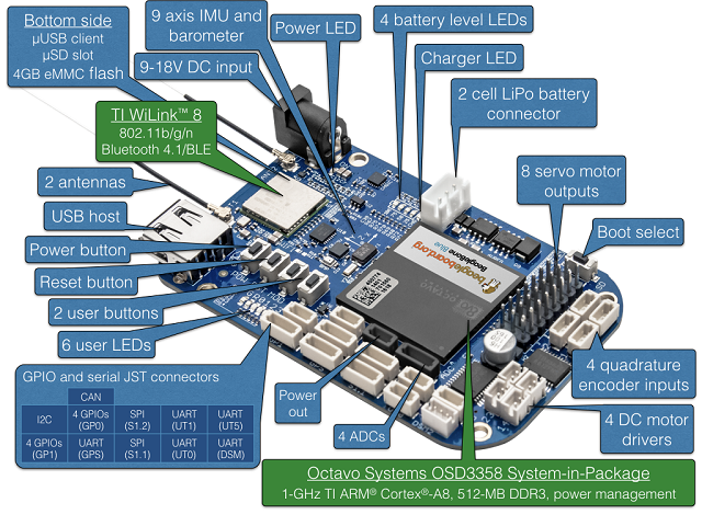
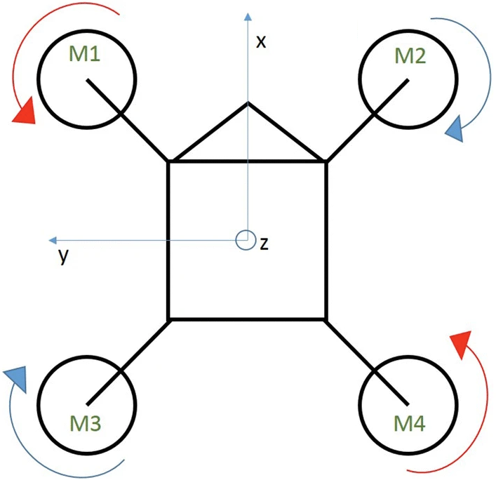
The Electronic speed controllers get connected to the first four slots of the “8 servo motor outputs” (see diagram below). These slots are labelled with very small lettering below the ports, you’ll see that servo output 1 is on the left-most side of the device. Make sure to connect the corresponding output to the associated ESC/motor as shown in the diagram below.
DSM Remote Receiver
Connecting the DSM remote receiver is quite simple. It connects to the port labelled UART (DSM) on the figure below. This is the only I/O port that fits the 3-wire JST ZHR-3 connector that is shipped with the DSM Remote Receiver
Mission Computer
The Optional mission computer connects to UART5, which is the I/O port directly above the DSM port. This port is intended to be used to send navigation feedback and trajectory commands via serialized mavlink messages.
Beaglebone Blue I/O Ports